Software Audit: Definition, Checklist and Comprehensive Guide
Dec 26, 2023
-19 min read

Software audit is a crucial routine checkup process to ensure your software’s health, safety, and compliance. By the end of this article, you will own a comprehensive handbook, covering from the most basic to the most complex knowledge surrounding software audits, offering valuable insights, best practices, and expert guidance to optimize your software assets and stay ahead in the ever-evolving technology industry. Let’s get cracking!
What Is Software Audit?
A software audit is a comprehensive process of examining a company’s software apps, systems, and licenses, performed by either an internal or external team, to ensure its compliance with legal requirements, industry standards, and other organizational policies.
During this process, to identify vulnerabilities, mitigate risks, and provide solutions for enhancing the software’s effectiveness, the software auditor will analyze various factors, including:
- License agreements
- Usage patterns
- Number of software app installations
- Potential instances of unauthorized or unlicensed software

There are three common methods for conducting the software auditing program:
- Internal audit software: The auditing software process is implemented by the in-house team regularly. This approach is best suited for businesses with well-established internal software audit processes and professionals possessing profound knowledge of the company’s software systems and structures.
- Third-party auditing software vendor: Software development companies contract with an external team to provide independent examination. This method is ideal for companies opting for an objective and unbiased evaluation.
- Collaborative software audit approach: This involves a collaboration of both internal and external auditing software teams. This method is highly recommended for complex audit projects that require a well-rounded evaluation, combining the internal team’s familiarity and the external team’s objective perspective.
Each method has its pros and cons that only help it shine in a specific scenario. To make an informed decision, your organization should consider your internal team’s capabilities and software audit goals.
Key Benefits of Auditing Software
According to Technavio’s latest report, “Audit Software Market – Forecast and Analysis 2023-2027”, the audit software market is calculated to increase at a CAGR of 13.36% between 2022 and 2027.
This outstanding growth in the market indicates that auditing software has substantial benefits to bring to the table. Let’s check out the significant advantages of performing software audits.

Effective license compliance management
Auditing software is vital for ensuring your software apps comply with licensing agreements and avoiding the risks of legal consequences and financial penalties.
When running a software application, businesses may struggle with keeping track of multiple licenses, subscriptions, and third-party integrations. Inactive licenses will damage your budget while using outdated ones can cause legal issues.
Regular auditing software allows your organization to:
- Avoid unnecessary expenses by identifying and removing outdated or unused licenses, and inactive subscriptions.
- Maximize software usage by identifying the current license state.
- Avoid legal issues by addressing outdated license contracts and deciding to extend or terminate them instantly.
Optimized software’s performance and quality
Auditing software is akin to a “health checkup” for your digital software applications. This process examines the software’s performance, addressing bottlenecks, and identifying areas for improvement.
At the nascent stage, regular software audit has a significant role to play in accelerating project delivery as developers can quickly detect flaws and adjust code with little to no negative influence on the whole system. Meanwhile, frequent audits during the normal operation of the software can give the development team an upper hand in optimizing software performance and eliminating inefficiencies with a view to smoothening user experience.
A comprehensive auditing software process allows you to address code quality issues, ensuring your software meets industry code standards, and reduces risks of bugs, ultimately leading to sustainable success.
Enhanced software security measures
Auditing software enables you to address your software’s security vulnerabilities. With early risk identifications, you can have an instant strategy to consolidate your digital defenses, thereby safeguarding sensitive data and eliminating cybersecurity threats.
In essence, auditing software acts as a proactive approach that protects your organization and improves customer trust.
Cost efficiency
With a well-rounded auditing software strategy, your organizations can acquire valuable insights into your software status regarding license and subscription state, usage patterns, etc. Based on the situation and context, you can optimize your budget by reducing unwanted expenses for overdated licenses, reallocating resources effectively, and renewing license contracts based on actual demands.
In addition, this insight enables you to make data-driven decisions for software upgrades, future investments, and emerging tech stack adoption. It empowers tech leaders not only in aligning technology initiatives with business goals, but also in creating software that meets the industry standards, drives innovation, and enhances competitive edge.

When Should You Perform a Software Audit?
Every software app and system requires regular auditing software to ensure the software’s health, security, and compliance. The software audit should be a regular task for a business. The recommended frequency is once or twice a year.
However, auditing software brings the most benefits and plays an important role in the software development life cycle when it comes to the following situations:

- When the software shows slow performance or no responsive
- When the software requires updates and new solutions after a long time
- When the software stops working as intended due to some security risks and needs instant issues identification for improvement
- When the need to reduce the budget arises
- Before deploying or launching software for end users
- When considering purchasing a software product and you want to review the product’s quality and performance
Common Audit Software Types
Depending on the software audit program’s specific goals, there are different types of software audits.

Software quality audits
As the name speaks for itself, software quality audit examines the quality aspects of software products. The software auditors will verify if your software apps and systems are up to date and function as intended.
In addition, software auditors will address bottlenecks, and room for improvement, and then recommend alternative solutions. This type of software audit is to assure that your software apps deliver flawless user experience and comply with the latest industry trends and standards.
Software security audits
A software security audit is essential for every software product, particularly in this era when cyber attacks have become increasingly commonplace.
Auditing software helps organizations take necessary precautions, and build digital defenses like malware protection, firewalls, SSL-encrypted data transmission, etc to safeguard their software from data breaches, security attacks, and other issues.
Software security audits might include conducting penetration tests, web app security tests, third-party application and integration security testing, etc.
Learn more about the differences among black box, grey box and white box penetration testing.
Software’s usability and accessibility audit
Ease of access and use determine your software’s success. Therefore, a usability and accessibility audit is vital before releasing your software to the market.
With a comprehensive software audit, auditors can address common issues like confusing onboarding, and overly complicated features, leading to awful user experience, and high bounce rates.
This software audit might include performing user flow analysis, heuristic evaluation, UI/UX test, etc.
How to Audit Software

Before auditing software
How to stay well-prepared before conducting the software audit? The preparation phase will set the foundations of the software audit project and determine its success. This phase involves the following steps:
- Identify the software audit’s goals: Clearly define the final objectives of the auditing software, whether it is to enhance software’s performance, ensure software compliance, or optimize costs.
- Develop software inventory: Create a comprehensive inventory of all installed software across your organization, including information on current licenses, usage, subscriptions, and software versions.
- Review existing software state: Evaluate all the current licensing agreements and compliance standards of your software to ensure that the audit aligns with legal requirements, eliminating oversights during assessment.
- Find the right auditing software vendor: If you opt for an external team to conduct your software audit, ensure you select a reputable vendor by evaluating carefully their experience, auditing tools, and expertise in the relevant domain.
- Assign roles and responsibilities: Clearly define responsibilities for each team member involved in the audit, such as data collection, data analysis, etc.
During the software audit process
To conduct an effective auditing software, this phase involves the following essential steps:
- Collect data automatically: Utilize automation tools to effectively and accurately scan and gather data from the entire system, including installed software, licenses, etc.
- Compare collected data with inventory list: Compare and identify any inconsistencies, then investigate the reasons, to ensure up-to-date information.
- Verify software licenses: Assess software license compliance, ensuring no overuse or underuse that could lead to unnecessary expenses or non-compliance.
- Assess software usage patterns: Analyze the current software usage, and identify overuse or misuse licenses to make necessary adjustments for improved software efficiency and compliance.
- Set up the audit: Create the audit infrastructure by defining the necessary audit parameters, and tools that align with the audit’s goals.
- Maintain communication with departments: Establish open communication channels and methods with involved departments, ensuring a transparent and collaborative audit process.
After the software audit process
This phase concentrates on synthesizing and analyzing results and establishing an ongoing improvement cycle. It involves the following steps:
- Collect detailed audit report: Compile audit results in a comprehensive report that provides detailed insights for stakeholders for future strategic decision-making.
- Conduct corrective actions: Based on the audit results, implement necessary corrective actions, involving uninstalling unauthorized software, modifying software usage patterns, and getting additional licenses.
- Update software inventory: Ensure that your software license and inventory are up-to-date, maintaining accurate records and eliminating discrepancies in future audits.
- Establish ongoing improvement strategy: Design a system for continuous monitoring, including setting up automated tools, regular checkpoints for compliance assessment, and revising policies.

Software Audit Checklist
A auditing software checklist is a useful guide for any internal or external audit team who are new to the process of software audit, ensuring no overused or misused steps. Here is a checklist for conducting a software audit:
- Clearly define objectives and scope to guide the auditing software process effectively
- Establish a well-structured auditing and testing plan for your software audit process, covering the specific timelines, sequence of tasks, and person in charge of each task, etc
- Compile a comprehensive inventory list of installed software, including detailed information like name, version, license type, installed date, and vendor information.
- Verify the licensing compliance, and identify any unauthorized software
- Examine the security measures, and address software vulnerabilities
- Review the contracts with external software audit vendors and other involved stakeholders to ensure compliance with terms for both sides
- Ensure that all the software apps are updated with the newest patches, and create a strategy for instant vulnerability mitigation
- Ensure your software usage patterns align with the organization’s policies and comply with the industry’s standards and requirements
- Evaluate and identify unnecessary software that might cause unwanted expenses to ensure cost-effectiveness
- Keep detailed and accurate documents and records of the audit process, including issues, actions taken during the assessment, etc
- Create a comprehensive report summarizing audit results and suggest actionable solutions for improvement
Software Audit Report: What Should Be Included?
An auditing software report is a comprehensive document that provides a summary of the audit findings, issues discovered, recommended improvement solutions, and plans for the next audit.

A general outline of a software audit might include the following common factors:
- Audit project overview: Summary of the audit, including key findings and recommended solutions for improvements.
- Audit project introduction: A brief and clear summary of the auditing’s objectives and scope.
- Audit methodology: Provide information about the tools, methods, and technologies used during the software audit.
- License compliance: Present a detailed report and analysis of the current software license state.
- Usage pattern: Assess and provide detailed software usage statistics against the licensing agreements.
- Software inventory assessment: Create a comprehensive inventory of all the software assets, including information regarding version, installed dates, etc
- Cost analysis: Calculate and estimate the overall budget of the software auditing project, and provide recommendations for optimizing the expenses.
- Conclusion: Provide the overall key findings, and outline the steps for the next auditing software process.

Frequently Asked Questions About Software Audit
1. What is audit software?
Software audit is the process of assessing, examining, and evaluating a software app to ensure its compliance with licensing agreements, define potential risks, and offer optimization solutions. This process can be conducted by an internal or external software auditor team.
2. Why regular software audit is important to your business?
Regular auditing software bring numerous advantages to your organization. It helps ensure that your software complies with its licensing agreements, avoiding legal and financial issues. Additionally, it allows your organization to optimize the software’s performance by detecting vulnerabilities, optimizing software usage, and providing recommendations for improvements. Lastly, regular auditing software bring cost-effectiveness by addressing overused, and unused software licenses and eliminating unwanted expenses.
3. How to audit software?
Conducting a software audit project involves the following essential steps: creating a software inventory list, evaluating security aspects, assessing licensing compliance, reviewing vulnerabilities, and offering optimization solutions. Documenting the entire auditing process is vital, including all the actions, findings, and suggestions. In essence, you should establish tailored software audit plans, including before, during, and after the process, aligning with your business’s goals and resources.
Final Thoughts About Audit Management Software
Software audit is a paramount process in every software development life cycle. It ensures that your software products comply with the license agreements, meet the industry standards, and align with the business requirements. A well-executed auditing software enables your organization to enhance efficiency, optimize budget, and eliminate risks.
With our comprehensive auditing software guide and checklist, you can have the best practices, and customize your own auditing software plans. LTS Group is a leading IT Outsourcing provider in Vietnam with extensive expertise in software development and software qualification assurance across platforms, devices, and industries. With 7+ years of experience, we ensure to provide you with a comprehensive and effective strategy for examining your software. Feel free to contact us for valuable insights, expert advice, and a roadmap to optimize your software audit strategy.
—
Website: https://ltsgroup.tech/
Tel: (+84) 96-238-7474
Linkedin: https://www.linkedin.com/company/lts-group-vietnam/
Share


Ashley Nguyen
Meet Ashley Nguyen, our dedicated Content Marketing specialist with a passion for digital transformation, AI, and software development. Ashley's words bridge the gap between complex tech concepts and everyday understanding. Her insightful pieces not only educate but also inspire readers to embrace the ever-evolving landscape of innovation. Join her in exploring the evolving landscape of technology and innovation. Contact her at ashley@ltsgroup.tech

More must-reads to keep leaders updated
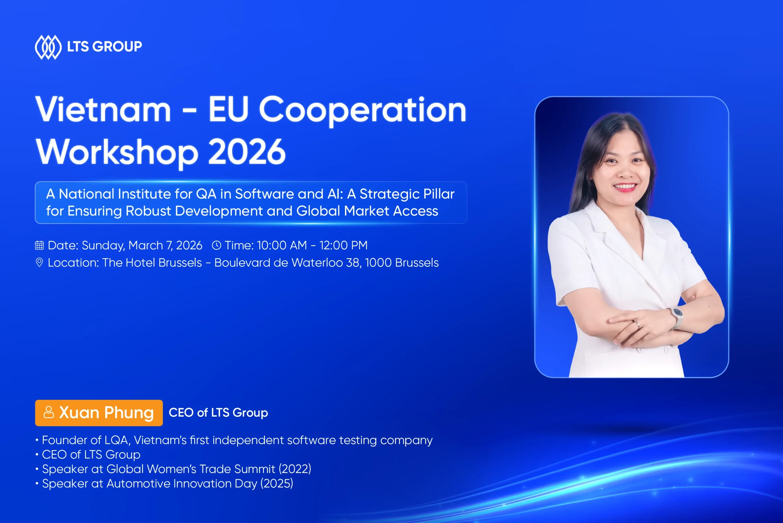
LTS Group CEO to Deliver Keynote at Vietnam – EU Cooperation Workshop 2026
Mar 4, 2026
-4 mins read
LTS Group is pleased to share that Mrs. Xuan Phung, CEO of LTS Group, will deliver a keynote address at the Vietnam – EU Science, Technology & Trade Workshop 2026, taking place on March 7, 2026 at The Hotel Brussels, Belgium. The workshop is organized by the Vietnamese Intellectual Association in Belgium and Luxembourg (ViLaB) and the Vietnamese Business Association in Belgium (VBAB), under the patronage of the Embassy of Vietnam in Belgium and Luxembourg. It brings together policymakers, researchers, and business leaders from Vietnam and across Europe to strengthen cooperation in science, technology, and trade. Table of Contents Toggle Event OverviewSpeaker IntroductionKeynote Session Event Overview Theme: Promoting Vietnam – EU Cooperation in Science, Technology and Trade Centered on strengthening Vietnam–EU cooperation, the workshop covers a range of strategic topics, including: Artificial Intelligence and Digital Transformation Biotechnology Nuclear Energy and Nuclear Medicine Trade and Business Collaboration More than a technical forum, the event aims to connect Vietnamese experts worldwide and foster practical partnerships between Vietnam and the European Union. With the shared vision of Connect – Innovate – Create, the workshop encourages cross-border collaboration to support sustainable growth and long-term innovation. Speaker Introduction Mrs. Xuan Phung is the Founder and Chairwoman of Lotus Quality Assurance (LQA), the first independent software testing firm established in Vietnam, which now has grown into an end-to-end IT services provider LTS Group. She founded the company in 2016 with a clear vision to build dedicated software quality engineering capabilities and elevate the role of quality in the global digital ecosystem. Starting from a small founding team, she has grown LTS Group into an organization of more than 500 professionals, with offices in Vietnam, Japan, South Korea, and the United States. Under her leadership, LTS Group has evolved from a specialized testing company into an international technology services provider, supporting clients across major global markets. Software quality engineering has remained at the core of the company’s identity, reflecting her long-standing commitment to building reliable, scalable, and trustworthy digital systems. As the Chairwoman, she continues to guide the company’s long-term vision, advocating for the strategic importance of quality. Keynote Session Mrs. Xuan Phung will co-present with Dr. Mai Xuan Phu, Quality Assurance Manager at Jemmic (Luxembourg) on the topic: “A National Institute for QA in Software and AI: A Strategic Pillar for Ensuring Robust Development and Global Market Access.” In this keynote, Mrs. Xuan will share perspectives drawn from industry practice on how Vietnam can strengthen its software quality ecosystem as it expands in global markets. The session will cover: Vietnam’s ICT growth and the shift toward quality-driven competitiveness Existing coordination gaps within the QA landscape The proposed role of a National QA Institute in aligning standards and capabilities How enterprises can contribute to a more unified and internationally recognized quality framework Through this contribution, LTS Group continues to advocate for elevating software quality engineering as a strategic driver of sustainable digital development. We look forward to engaging with partners, experts, and industry leaders at the workshop and contributing to meaningful dialogue on advancing Vietnam–EU collaboration in technology and innovation. Date: Sunday, March 7, 2026 Time: 10:00 AM – 12:00 PM Location: The Hotel Brussels, Boulevard de Waterloo 38, 1000 Brussels, Belgium
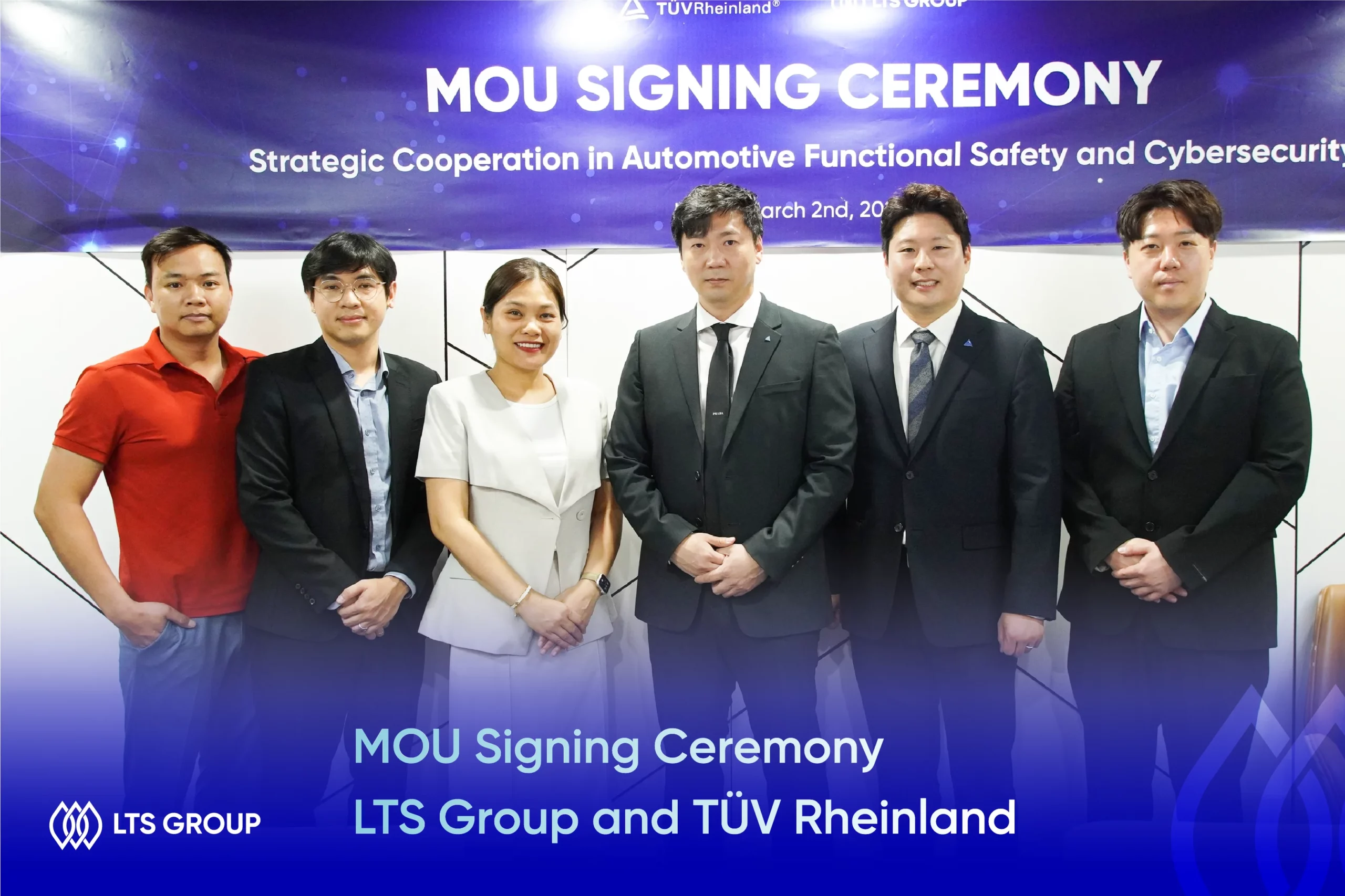
TÜV Rheinland and LTS Group Sign Strategic Partnership to Deliver Cybersecurity and Functional Safety Testing Services
Mar 3, 2026
-4 mins read
On March 2, TÜV Rheinland, a global leader in testing, inspection, and certification, officially signed a Memorandum of Understanding (MOU) with LTS Group to collaborate in delivering cybersecurity and functional safety testing services. During the signing ceremony, both parties discussed key areas of cooperation, including testing talent development and the operational collaboration model. Through this strategic partnership, LTS Group and TÜV Rheinland aim to combine global certification expertise with strong technical testing capabilities to provide high-quality software testing services that meet international standards. Founded in 1872, TÜV Rheinland is a leading global provider of testing, inspection, and certification services. The organization operates a worldwide network of accredited laboratories, training centers, and inspection bodies, supported by approximately 27,000 employees across offices in more than 50 countries. TÜV Rheinland tests and certifies technical equipment, products, and services while also supervising projects, processes, and information security for enterprises across industries. Its experienced experts provide professional training and workforce development programs for a wide range of sectors. Since 2006, TÜV Rheinland has been a member of the United Nations Global Compact, demonstrating its commitment to sustainability and ethical business practices. The company’s services are centered around four core areas: industrial services and cybersecurity, mobility, product quality and safety, and people and business assurance. Founded in 2016, LTS Group is a global full-cycle IT services and high-quality IT staffing provider. The company operates five member companies and maintains international branches in the United States, South Korea, and Japan. Its subsidiary, Lotus Quality Assurance (LQA), is recognized as Vietnam’s first independent software testing company, delivering reliable testing services backed by experienced professionals. Over nearly a decade, LTS Group has served more than 60 clients across 11 countries, successfully completed 275 projects, and achieved a 97% customer satisfaction rate. This MOU marks an important milestone in LTS Group’s continued commitment to enhancing service quality and expanding its global partnership ecosystem. Mr. Jin Pyo Noh, representative of TUV Rheinland, shared, “At TÜV Rheinland, we emphasize precision in both assessment and implementation. Through our collaboration with LTS Group, we combine that precision with strong local engineering capabilities to support customers in addressing safety and cybersecurity challenges in a structured and sustainable way. In today’s increasingly complex automotive systems, achieving Functional Safety and Cybersecurity requires integrating safety and security into system design from the outset. Beyond technical alignment, we believe successful partnerships are built on shared values and mutual trust. That is what makes this collaboration in Vietnam particularly meaningful for us as we strengthen safety capabilities across the Asia Pacific region.” Mrs. Xuan Phung, CEO of LTS Group, stated, “We are proud to partner with TÜV Rheinland APAC to further strengthen our commitment to quality in the automotive sector. By combining TÜV Rheinland’s training and certification expertise with LTS Group’s experience in automotive software development and validation, we aim to deliver a comprehensive solution covering process consulting, engineer training, technical assessment, and certification. It is also a wonderful opportunity for Vietnamese automotive talents to dive deep into world-class standards for Functional Safety and Cybersecurity.”
ADAS: A Complete Guide to Advanced Driver Assistance Systems
Oct 29, 2025
-33 mins read
Among the technologies shaping the future of mobility, the Advanced Driver-Assistance System (ADAS) stands as a cornerstone for achieving fully autonomous driving. As vehicles evolve into intelligent, connected platforms, ADAS is redefining what safety, comfort, and performance mean on the road. Driven by breakthroughs in AI, sensor fusion, and V2X (Vehicle-to-Everything) connectivity, ADAS systems enable vehicles to sense, interpret, and act on complex driving environments in real time. Features such as adaptive cruise control, automatic emergency braking, and lane keeping assist are now integral to modern vehicle design, reflecting the industry’s shift toward software-defined intelligence. Behind these innovations lies a sophisticated software ecosystem demanding precision, scalability, and compliance with strict safety standards like ISO 26262. With deep expertise in automotive software development and testing based on the V-Model, LTS Group provides tailored engineering solutions that empower global OEMs and Tier 1 suppliers to accelerate ADAS development efficiently and reliably. In this article, we uncover the foundations and technologies behind ADAS, and explore how advanced software engineering is paving the way toward a safer, smarter, and fully autonomous future. Table of Contents Toggle What is ADAS?Overview and functionalityDevelopment historyApplication areas of ADASMarket size and future outlookLTS Group Automotive Software Development and Test Solutions (V-Model Compliant)Software requirements analysis Software architecture designSoftware detailed design and unit implementationSoftware unit testingSoftware integration testingSoftware conformance testingLTS Group’s Automotive Software Development and Testing Case StudyDeveloping driving safety and energy management solutions for a Chinese tier-1 supplierWhy Choose LTS Group’s Automotive Software Engineers1. Internationally compliant development and quality management system2. Over 8 years of specialized experience in automotive software development3. Proven track record: 250+ projects, 15,000+ man-months of experience4. Agile, scalable organization with rapid decision-makingFrequently Asked Questions About ADASConclusion What is ADAS? Advanced Driver-Assistance Systems (ADAS) refer to vehicle-based intelligent safety technologies designed to enhance road safety, improve driving comfort, and support the transition toward autonomous mobility. By leveraging advanced sensors, control algorithms, and embedded software, ADAS helps prevent accidents, reduce their severity, and facilitate more efficient post-accident response. Overview and functionality At its core, ADAS is a software-driven ecosystem that enables vehicles to perceive, interpret, and respond to their surroundings in real time. Using a combination of cameras, radar, LiDAR, ultrasonic sensors, and sensor fusion algorithms, these systems identify road signs, pedestrians, nearby vehicles, and lane markings with high precision. The collected data is processed through real-time decision-making algorithms that either alert the driver or automatically take corrective action. Common examples include: Forward Collision Warning (FCW) and Automatic Emergency Braking (AEB) to prevent frontal impacts. Lane Departure Warning (LDW) and Lane Keeping Assist (LKA) to maintain lane discipline. Adaptive Cruise Control (ACC) to automatically adjust speed and maintain a safe following distance. Blind Spot Detection (BSD) to monitor adjacent lanes. Automated Parking Assist (PA) to support precise, hands-free maneuvering. Together, these systems contribute to an integrated safety environment, combining human intuition with machine intelligence to reduce driver workload and enhance situational awareness. Development history The origins of ADAS trace back to the early 1990s in Japan, where automakers such as Toyota and Mitsubishi pioneered radar-based Adaptive Cruise Control (ACC) systems. This innovation automatically adjusted vehicle speed to maintain safe distances, marking one of the first practical steps toward intelligent driving assistance. During the same period, European and American manufacturers were still limited to conventional cruise control. It was not until the mid-2000s that advanced systems such as ACC, Blind Spot Detection (BSD), and Park Assist (PA) began to appear in high-end models from Mercedes-Benz, BMW, and Lexus. The terminology “Advanced Driver-Assistance Systems (ADAS)” gained official recognition in 2014, when global regulators, research institutions, and OEMs began standardizing definitions and safety requirements across the automotive sector. This milestone reflected a growing consensus: intelligent software, not just mechanical precision, would define the next era of automotive safety. Year Milestone Description 1958 First constant-speed control Chrysler introduces the first cruise control system in the U.S. 1992 Japan’s radar-based ACC experiments Toyota and Mitsubishi begin adaptive speed control testing. 1995 Intelligent highway system (IVHS) Europe and the U.S. expand smart vehicle R&D initiatives. 2003-2006 Commercialization of ADAS features ACC, BSD, and PA systems enter luxury models. 2010s Emergence of sensor fusion Camera-radar integration evolves into AI-based decision making. 2014 Global standardization of “ADAS” Official adoption of the term by industry and academia. 2020s Widespread adoption and Level 2 autonomy Systems like Tesla Autopilot and Hyundai SmartSense popularize assisted driving. Application areas of ADAS Originally designed for passenger cars, ADAS technologies are now widely adopted across commercial, industrial, and agricultural vehicles, each with tailored use cases: Public transport: Buses and trams equipped with AEB, LKA, and FCW help reduce urban accidents and improve pedestrian safety. Heavy-duty trucks: Blind Spot Detection (BSD) and Adaptive Cruise Control (ACC) enhance long-distance safety and efficiency, especially on highways. The EU’s 2024 regulation mandating ADAS in new commercial vehicles underscores its growing importance. Construction and off-road machinery: Systems like work radius detection, automatic stop, and slope assistance protect workers and improve operational efficiency in demanding environments. Agricultural machinery: GPS- and LiDAR-based driving assistance enables automated tractors, autonomous harvesters, and drone-integrated crop monitoring, forming the backbone of precision agriculture. This diversification highlights the scalability of ADAS, from consumer vehicles to specialized equipment, powered by adaptable software architectures and domain-specific algorithms. Market size and future outlook According to Statista, the global ADAS market reached approximately USD 58 billion in 2024 and is expected to surpass USD 125 billion by 2029, reflecting a strong CAGR driven by rising safety regulations and demand for automation. In the Asia-Pacific region, growth is projected to outpace all other markets between 2025 and 2030, led by expanding vehicle production, infrastructure development, and strong OEM presence in China, India, and Japan (Grand View Research). China currently holds the largest market share, driven by rapid smart mobility initiatives. India is forecasted to achieve the fastest CAGR, emerging as a key innovation and manufacturing hub. Leading ADAS solution providers, such as Bosch, DENSO, Valeo, Continental, and Mobileye, continue to invest in AI-driven perception, sensor integration, and software modularization to meet growing regulatory and performance expectations. The market’s trajectory indicates a clear trend: as vehicles become software-defined, ADAS will no longer be an optional feature but a fundamental system layer. The convergence of sensor technology, data analytics, and embedded software engineering is shaping the foundation for higher levels of automation and safer, more connected mobility ecosystems. LTS Group Automotive Software Development and Test Solutions (V-Model Compliant) LTS Group adopts a systematic and safety-oriented software development and verification process based on the internationally recognized V-Model, designed to meet the automotive industry’s most rigorous functional and safety requirements. The V-Model establishes a one-to-one correspondence between development and testing activities, ensuring every function is validated against its intended specification, ranging from initial requirement analysis to final system qualification. By aligning each phase of the software lifecycle with its verification counterpart, LTS Group secures predictable, measurable, and high-assurance quality outcomes, minimizing downstream risks and optimizing time-to-market. This section outlines the step-by-step execution framework that LTS Group applies in real-world customer projects, showcasing how our V-Model–compliant development process enables the creation of robust, standards-compliant automotive systems such as ADAS, ECUs, and domain controllers. Software requirements analysis In the Software Requirements Analysis (SRA) phase, LTS Group performs a comprehensive examination of the system and software specifications provided by OEMs. Our engineers meticulously extract, structure, and refine these requirements to establish a clear and verifiable foundation for all subsequent development stages. This phase is essential to ensuring that each functional feature is implemented accurately and aligned with the intended vehicle system behavior. Our systematic approach includes: Requirement extraction & structuring Thoroughly analyze system and software specifications provided by OEMs. Abstract and formalize requirements into a structured Software Requirements Specification (SRS) document. Establish a solid basis for accurate, error-free feature implementation in subsequent stages. Requirement classification & refinement Categorize requirements by level, function, and data interaction. Perform linguistic and logical refinement to eliminate ambiguity or overlap. Ensure consistency and clarity across all stakeholders, minimizing misinterpretation. Stakeholder collaboration & validation Maintain continuous, two-way communication with OEMs and suppliers. Clarify scope, constraints, and assumptions through consultative discussions. Proactively identify and mitigate potential project or compliance risks. Traceability & change management Apply ASPICE-compliant bidirectional traceability to link requirements with implementation and verification activities. Utilize IBM DOORS, an industry-standard tool, for transparent requirements management. Control modifications through version tracking, baseline management, and change review processes. These methodologies have been successfully applied in our large-scale automotive programs, including ESP/ESC/IBS systems and BMW Battery Management Systems (BMS) – demonstrating LTS Group’s reliability and technical competence as a software development partner in the highly regulated automotive domain. Software architecture design The Software Architecture Design phase transforms system requirements into a structured, technically feasible software framework. This stage is fundamental to ensuring that each automotive software system, particularly those supporting ADAS, chassis control, or battery management, achieves high performance, reliability, and scalability across its lifecycle. Our process combines methodological rigor with hands-on engineering expertise, following ASPICE-aligned practices and ISO 26262 functional safety standards. Key execution areas System decomposition and modular design Decompose the complete system into independent, function-specific modules with clearly defined responsibilities and boundaries. Map data and signal flows between modules to maintain consistency, timing precision, and interoperability. Define standardized interfaces and APIs to enable seamless integration between hardware and software components, including ECUs and domain controllers. Architecture modeling and tool-based validation Utilize IBM Rhapsody and Vector DaVinci for model-driven architecture design, simulation, and validation. Align the software structure with the hardware topology, ensuring parallel development and streamlined debugging. Maintain full traceability from requirements to architectural elements, ensuring compliance with ASPICE process maturity. Integration for ADAS and safety-critical applications Architect integrated systems combining 77GHz radar, cameras, LiDAR sensors, and domain controllers to support real-time data fusion and perception. Optimize for real-time response, bandwidth efficiency, and fault-tolerant design – core prerequisites for safety-critical automotive systems. Design architectures that ensure deterministic behavior and redundancy in line with ISO 26262 requirements. Layered architecture approach Structure the system into application, service, and communication layers to maximize reusability and maintainability. Facilitate modular updates and future scalability, supporting evolving E/E architectures and emerging connectivity standards. Proven applications LTS Group’s architecture design capabilities have been successfully implemented in a range of complex, real-world automotive projects, including: Daimler Loop Controller Domain Controller for ADAS (77GHz Radar, Camera, and LiDAR Integration) ESP/ESC/IBS Smart Chassis Controller Airbag Control Unit Battery Management System (BMS) PEPS (Passive Entry Passive Start) System Software detailed design and unit implementation This stage focuses on translating each architectural element into detailed designs, configurations, and implemented modules that adhere to AUTOSAR standards, functional safety, and cybersecurity requirements. Our engineers employ model-based design, automated configuration, and systematic validation to ensure that every software unit integrates seamlessly into the overall system architecture. Key execution areas Detailed module design and specification Develop precise design specifications for each functional module, based on the previously defined system and software architecture. Use IBM Rhapsody to model control logic, data structures, and state machines, ensuring clear traceability to system requirements. Define module-level interfaces and data exchange mechanisms to maintain consistency across communication layers and ECUs. AUTOSAR-based development and configuration Utilize Vector DaVinci Developer and DaVinci Configurator Pro to design and integrate Basic Software (BSW) components within the AUTOSAR environment. Configure the Microcontroller Abstraction Layer (MCAL) via EB Tresos, enabling stable hardware–software interaction and precise peripheral control. Implement and configure standard automotive services and protocols, including OS, UDS, UDSonCAN, NVM, E2E, NM, XCP, CDD, RTE, and DEM – each aligned with timing and communication constraints defined in earlier design phases. Custom bootloader and cybersecurity implementation Design and implement OEM-specific bootloaders that comply with cybersecurity and secure boot requirements, ensuring software authenticity and integrity. Enable secure over-the-air (OTA) updates and in-field reprogramming to support long-term system maintainability. Functional safety integration and validation Integrate functional safety mechanisms at the unit level to meet ISO 26262 compliance targets. Apply defensive programming and diagnostic monitoring strategies to prevent cascading system faults and ensure safe degradation behavior. Conduct static code analysis, unit testing, and coverage validation to verify each unit’s logical correctness and adherence to design intent. Tools utilized LTS Group leverages a comprehensive suite of industry-standard tools to ensure precision, consistency, and full compliance throughout the detailed design and implementation phase: IBM Rhapsody – Model-based design and requirement traceability Vector DaVinci Developer & Configurator Pro – AUTOSAR BSW design, configuration, and validation EB Tresos – MCAL configuration and hardware abstraction management GENy – Configuration of Classic AUTOSAR modules and service layer components Proven deliverables Through this systematic, tool-driven approach, LTS Group warrants that every software unit is: Functionally aligned with system-level requirements Configured for seamless hardware integration Verified for both safety and cybersecurity compliance Ready for downstream testing and system integration under the ASPICE V-Model framework Software unit testing In the Software unit testing phase, each software module is rigorously verified to ensure that it performs its intended functions accurately, consistently, and safely. This phase serves as a critical quality gate in the automotive software development lifecycle, allowing defects to be detected and corrected at the earliest possible stage – before system integration, to significantly enhance overall reliability and reduce rework costs. Key objectives and approach Early error detection and verification Validate each software unit’s functional behavior, logical flow, and safety mechanisms in isolation. Ensure each unit meets the defined software requirements and design specifications established in earlier phases. Identify potential issues such as data handling errors, timing conflicts, or control logic flaws before integration. Dynamic testing (SIL / MIL-based verification) Conduct Software-in-the-Loop (SIL) and Model-in-the-Loop (MIL) simulations to replicate the runtime environment and validate module-level functionality under realistic conditions. Utilize specialized tools, including TPT, Tessy, and VectorCAST for: Automated test case generation Batch execution and regression testing Real-time result analysis Coverage measurement across MCDC (Modified Condition/Decision Coverage), Branch, and Decision criteria that complies with functional safety requirements under ISO 26262. Static analysis for code quality assurance Perform static code analysis in parallel using Polyspace and QAC to identify potential vulnerabilities before execution. Detect and correct critical issues such as: Uninitialized or unused variables Pointer misuse and memory access violations Logic inconsistencies and control flow anomalies MISRA C compliance violations and deviations from industry-accepted safety coding standards Traceability and compliance Maintain bidirectional traceability between test cases, requirements, and design elements through automated tool integration. Document and review all unit test outcomes as part of ASPICE process compliance and ISO 26262 evidence generation. Tools utilized Dynamic testing tools: TPT, Tessy, VectorCAST SIL (Software-in-the-Loop), MIL (Model-in-the-Loop) Static testing tools: Polyspace, QAC Proven application These unit-level verification activities have been successfully applied in projects involving ECUs, domain controllers, airbag controllers, and ADAS systems, ensuring predictable reliability, safety integrity, and production readiness across all software components. Software integration testing The software integration testing phase validates the correct interaction and communication between software modules that have successfully passed unit testing. This stage serves as a crucial checkpoint to guarantee that individually verified modules, when integrated, operate cohesively and reliably within the complete software environment. The ultimate goal is to confirm functional correctness, interface integrity, and system stability before system-level validation. Key objectives and approach Ensuring seamless module interaction Verify that modules exchange data, signals, and control commands as defined in the software architecture design. Detect and resolve integration defects such as interface mismatches, data corruption, or timing inconsistencies early in the testing pipeline. Confirm that inter-module communication meets real-time performance and safety constraints required for automotive applications. Interface testing Utilize tools such as Lauterbach and Tessy to validate the correctness of interface definitions and data exchanges between modules. Focus on interface boundary verification to ensure accurate communication between application software (ASW) and basic software (BSW) layers, as well as between middleware and hardware abstraction layers. Apply this especially to ECUs, ADAS domain controllers, and airbag control systems, where microsecond-level synchronization and deterministic responses are critical. Back-to-back testing Conduct Back-to-Back (B2B) Testing using tools like Tessy and TPT, comparing outputs between two environments, such as model simulation and target hardware, for the same input stimuli. Detect any logical discrepancies or behavioral deviations caused by integration issues, ensuring that the software performs consistently across development and production environments. Validate that compiled binaries accurately represent the modeled logic, eliminating inconsistencies that could compromise safety or performance. Traceability and compliance Maintain complete traceability between test cases, integration scenarios, and corresponding software requirements. Record and manage all integration test results in accordance with ASPICE and ISO 26262 guidelines for safety-critical verification evidence. Tools utilized Interface Testing: Lauterbach, Tessy Back-to-Back Testing: Tessy, TPT Proven application This integration testing framework has been successfully implemented in complex automotive software projects, including ADAS domain controllers, chassis control systems, and airbag ECUs, for robust interoperability, timing precision, and safety integrity before proceeding to full system validation. Software conformance testing The software conformance testing phase serves as the final verification step in the V-Model process, verifying that the fully integrated software system meets all functional and non-functional requirements defined in earlier development phases. This testing is conducted at the system level using quantitative and standardized methods, marking the final validation milestone before OEM approval or customer delivery. Objectives and key focus Validation of system compliance Confirm that the complete software system performs according to defined functional specifications, performance metrics, and safety criteria. Verify that real-time responses, communication protocols, and diagnostic functions align precisely with OEM requirements and international automotive standards. Evaluate non-functional parameters such as timing accuracy, resource utilization, and fault tolerance to ensure robust and predictable behavior under real-world conditions. Automation-driven testing framework Execute automated Software Conformance Tests using Vector vTESTstudio, integrated with the CANoe simulation environment. Develop and run Python- and CAPL-based test scripts, enabling extensive scenario coverage, repetitive test execution, and efficient regression testing. Automate diverse input variations and environmental conditions to guarantee repeatability, accuracy, and reliability in test outcomes. Real-time monitoring and analysis Monitor the target system’s operational state via the XCP interface, observing live data exchange and behavior under different test stimuli. Capture, analyze, and visualize system responses in real time to promptly detect functional deviations or performance bottlenecks. Record all test results in standardized formats, ensuring transparent traceability and auditable compliance for project documentation and OEM validation. Traceability and reporting Link each conformance test to its corresponding requirement through a bidirectional traceability matrix, in accordance with ASPICE and ISO 26262 guidelines. Generate structured reports that provide a quantitative overview of pass/fail criteria, error logs, and verification coverage – supporting OEM acceptance processes. Tools utilized Testing framework: Vector vTESTstudio, CANoe Scripting and automation: Python, CAPL Monitoring interface: XCP Proven application This conformance testing approach has been successfully applied to ECUs, domain controllers, airbag systems, and BMS modules, ensuring that each delivered software system is functionally validated, safety-compliant, and production-ready – meeting the stringent quality expectations of global automotive OEMs. LTS Group’s Automotive Software Development and Testing Case Study Developing driving safety and energy management solutions for a Chinese tier-1 supplier Customer overview The client is a Chinese automotive technology company that develops and supplies a range of driving safety and energy management solutions, including airbags, cameras, ADAS modules, and power systems, for major global OEMs. Business challenges While expanding operations to Vietnam, the client encountered significant challenges in establishing a legal local entity, controlling operational costs, and maintaining project timelines. To address these issues, LTS Group proposed a Build-Operate-Transfer (BOT) model, enabling the client to quickly establish a legally compliant, cost-efficient, and scalable development center in Vietnam with long-term operational support. Scope of work Safety systems Airbag, camera, radar, and lidar development Advanced Driver Assistance Systems (ADAS) and Adaptive Cruise Control (ACC) Electronic Stability and Attitude Control Systems Steering and braking systems Powertrain & energy systems Engine and powertrain management Fuel and energy systems Major projects Development of a secure bootloader for safety systems Team size: 4 engineers Duration: Mar 2023 – Sep 2023 Development of BSW and MCAL for airbags, steering locks, braking systems, and radar cameras (ESP/ESC) Team size: 5 engineers Duration: Feb 2023 – Feb 2024 MATLAB and SIL design for horn control systems Team size: 6 engineers Duration: Jan 2024 – Feb 2024 Development of BSW and MCAL layers for zone ECUs Team size: 10 engineers Duration: Mar 2023 – Mar 2024 Technologies & tools Core technologies: BSW, MCAL, AUTOSAR, ASPICE Level 2, SHA-256 Tools: Vector vFLASH, vTESTstudio, VectorCAST, MATLAB, Simulink, Helix QAC Configuration: MCAL setup in C, CAPL, DaVinci Configurator & Developer, EB Tresos Additional components: Bootloader development, iSYSTEM debugger Why Choose LTS Group’s Automotive Software Engineers 1. Internationally compliant development and quality management system LTS Group operates under a systematic development and quality assurance framework fully aligned with international automotive software standards, including AUTOSAR, ASPICE Level 2+, ISO 26262 (Functional Safety), ISO 15765, and ISO 14229. These globally recognized standards are the backbone of modern automotive software engineering, ensuring safety, interoperability, and reliability across vehicle systems. By adhering to these frameworks, LTS Group guarantees that its deliverables meet the stringent compliance and quality expectations of global OEMs and Tier 1 suppliers. At the heart of our process lies ASPICE (Automotive SPICE), which measures the maturity of the software development lifecycle. Through this framework, LTS Group maintains: Clear and traceable requirements definition to prevent ambiguity and scope drift. Systematic architecture design to ensure scalability and consistency. Structured integration and verification testing aligned with the V-Model. Rigorous review and feedback loops to ensure predictable, stable quality outcomes. This disciplined, traceable approach allows our clients to achieve global-level quality control, ensuring reliable performance from requirement changes to functional safety validation. 2. Over 8 years of specialized experience in automotive software development With over eight years of hands-on experience in automotive software development and validation, LTS Group has accumulated deep expertise across diverse domains. Our engineers understand not only the technical complexities of embedded systems but also the process-driven requirements of global OEMs and Tier 1 suppliers. Our expertise spans across: Advanced Driver Assistance Systems (ADAS) Battery Management Systems (BMS) Airbag Controllers and Smart Chassis Systems Roof and Body Controllers Beyond functional implementation, our teams excel at logic design integrated with real-world vehicle environments and early safety analysis, ensuring robust performance even in mission-critical systems. This experience-based know-how empowers clients to minimize risks, reduce rework, and accelerate time-to-market, fostering seamless collaboration across every stage, from concept planning to production launch. 3. Proven track record: 250+ projects, 15,000+ man-months of experience LTS Group’s engineering excellence is backed by over 250 successful projects and 15,000+ cumulative man-months of delivery experience. This extensive portfolio covers high-complexity areas such as ECU software, functional safety modules, and vehicle communication systems. Our focus goes beyond development delivery: We aim to create measurable business value for clients by achieving: Shorter product release cycles through optimized workflows and reusable assets. Reduced defect rates via robust testing automation and ASPICE-driven quality management. Enhanced maintainability enabled by reusable templates, standardized documentation, and traceable artifacts. This proven reliability is why leading OEMs and Tier 1 suppliers continue to entrust LTS Group with their core automotive software projects, even under tight timelines and complex requirements. 4. Agile, scalable organization with rapid decision-making With a mid-sized structure of approximately 500 professionals, LTS Group strikes the perfect balance between organizational maturity and operational agility. Our lean management model enables fast, hands-on decision-making – avoiding the bureaucratic delays often found in larger corporations. Key advantages include: Rapid response to requirement changes or issue escalation directly at the project site. Flexible, collaborative engagement from meeting and review to on-the-fly implementation. Transparent project oversight, supported by monthly progress evaluations and regular performance reviews. This agility allows LTS Group to adapt quickly to client needs while maintaining consistent quality, ensuring seamless collaboration and long-term trust-based partnerships. Frequently Asked Questions About ADAS 1. What is Automotive ADAS? ADAS (Advanced Driver Assistance Systems) refers to technologies designed to improve driving safety and comfort. By leveraging sensors, cameras, and intelligent algorithms, ADAS detects obstacles, monitors driver behavior, and automatically assists with braking, steering, or acceleration. It serves as the foundation for autonomous driving systems and plays a vital role in advancing future mobility. 2. Is it possible to carry out automotive IT outsourcing projects in Vietnam? Absolutely. Vietnam’s outsourcing industry has expanded well beyond basic development services to include specialized automotive software engineering. Companies like LTS Group have successfully delivered projects in ECU development, Model-Based Development (MBD), and test automation for major Tier-1 suppliers and OEM partners worldwide. 3. How is the quality of Vietnamese talent in the automotive software field? Vietnam is quickly emerging as a hub for skilled automotive software engineers. By 2030, an estimated 2.7 million tech graduates will enter the workforce, with over 50,000 individuals annually trained in embedded systems, AI, robotics, and automotive software. Many possess certifications in AUTOSAR, ISO 26262, and ASPICE, along with strong communication skills in English, Korean, and Japanese, making them a strong fit for global development projects. Conclusion ADAS represents not only the foundation of autonomous driving but also a driving force behind the future of intelligent mobility. Through this article, we’ve explored the significance of advanced driver assistance systems and how LTS Group’s V-model–based software development and testing solutions deliver quality, reliability, and scalability across automotive platforms. With a strong track record, global-standard quality assurance, and an agile engineering team, LTS Group continues to partner with leading automotive companies to deliver innovation and safety-driven results. If your company is seeking a trusted partner for automotive software development and testing outsourcing in Vietnam, LTS Group offers the expertise, efficiency, and stability you can rely on.


Email:contact@ltsgroup.tech
Phone:(+84) 96-238-7474
Headquarters:17th Fl, MD Complex Office Building, 68 Nguyen Co Thach Street, Hanoi, Vietnam
Japan office:5F, Iwamoto Building, 3-20-10 Shibaura, Minato-ku, Tokyo 108-0023, Japan
US office:25787 Rawley Springs Dr, Chantilly, VA 20152
Korea Office:Seoul, Seocho-gu, Gangnam-daero 327, 12Fl, Room 1214